Building the Jupiter ACE+ (By Cees Meijer)
by Stephen Gillespiepublished on

Collecting vintage computers can become addictive but it is a great way to learn and it’s fun. (although that is possibly a personal opinion 😊 This project was brought to my attention my James and more information from the designer Cees (website) and James can he found here on Hackaday.
Luckily quite a few issues have already been found and resolved so hopefully my build will be a bit easier. I’m still very new to electronics so this is a big learning curve.
A Bill Of Materials can be found here. This is based on my build and what I had available.
There are a few minor issues with the board which are discussed in the Hackaday post. I have also made note of them below together with some additional information which I think may be helpful.
- Choke L1
- Power supply is 9v using a 3.5mm jack plug with the tip negative. The connector which goes on the board has four contacts but only one is connected to the ground on the board. It’s always best to double check your power supply before adding ICs on the board.
- R27 appears twice.
- R53 is next to TP1. It’s not easy to read on the PCB
- C15 is next to U17. Also, not easy to read
- C9 is an electrolytic capacitor with the negative to ground. The positive trace goes to D16 which can be easily seen on the reverse of the board.
- LM7805 – I used a little switch mode regulator supplied by James as it runs much cooler.
- R7 specifies 1k but I am using 750 and it has also been shown to work with 680.
- J8 does not need to be set if using a 27c512. Join pins 1 and 4 for a 27c256 to a15 (vpp) to 5v.
Programming the 27C512 EPROM. I decided not to take a risk with what area of the ROM will be used and copied the ROM Eight times to fill the 27C512. 😊 See below for the Windows DOS command. I used a TL866II Plus for the job.
| C:\Users\gille\Google Drive\Retro\Jupiter Ace>copy /b ace.rom + ace.rom + ace.rom + ace.rom + ace.rom + ace.rom + ace.rom + ace.rom ace512.rom ace.rom ace.rom ace.rom ace.rom ace.rom ace.rom ace.rom ace.rom 1 file(s) copied. |
My build, problems, and solutions.
I was lucky to have help from James as I built my Jupiter, and I needed it. 😊 I’m new to electronics so have made a few mistakes.
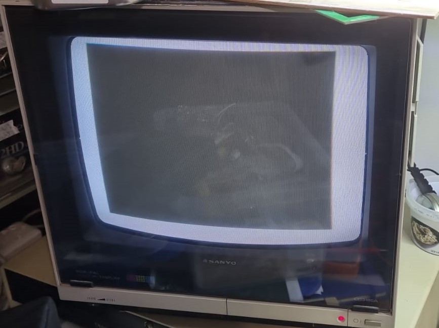
The first mistake major mistake showed itself after I was able to confirm I was getting a video signal. I confirmed I had a video signal by running with the composite video soldered directed to the output of D14 and the ground of the video out. It produced this which at least showed there was a signal.
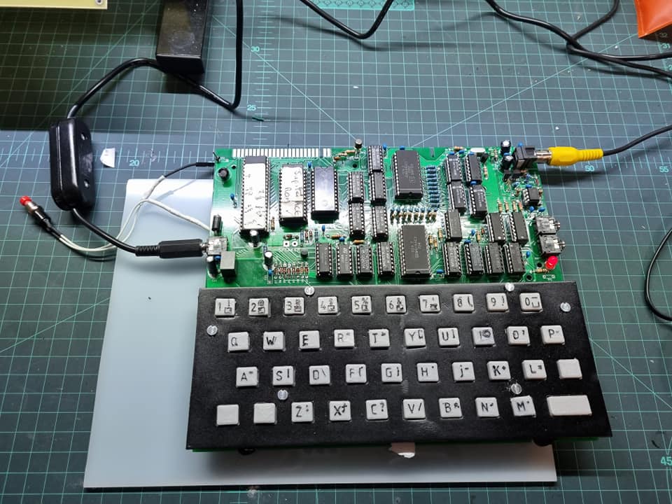
After inserting the LS166 and the other chips except the ROM and CPU, I got this which was good. The only issue is that the video if shifted to the left. This is also a problem reported by James.

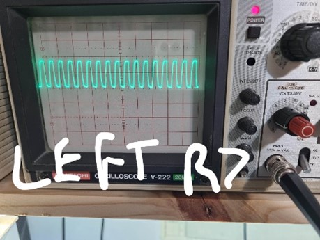
The first issue I had was with the clock circuitry around Q2. I was not getting a clock signal at pin 6 of the CPU which pointed the finger at Q2 (2N2369) and the components around it. R8 (270 Ohm) connects to VCC and Pin 3 of Q2 and to pin 6 of the CPU. Pin 2 (base) connects to R7 (Specified at 1k, but I ended up using 750 Ohm) as Q2 was not firing with the 1k. Pin 1 of Q2 goes to ground. Capacitor C4 connects to each side of R7 and is a 47pF ceramic resistor.
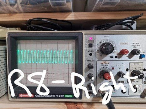
The pad for Q2 is very tight and I had initially soldered in the 2N2369 the wrong way round. It should be inserted with the little tab on the “tin lid” facing to the bottom right of the board. I replaced Q2 but still didn’t have a clock. After many hours debugging this with help from James virtually and then in person, it seems there was a bad connection somewhere as re-flowing all the joints eventually resulted in a clock signal. See below for the signals you should have. When the connections were not good, I had issues like a low amplitude clock, a clock with a strange wave form, and also no-clock.
At this point, I had a clock at the CPU and the CPU appeared to be running but I still had a screen full of junk. ☹
Call the experts.... :-)
A special thank you to James Higgs who spotted my mistakes. He discovered that all the resistors that are supposed to be 1k, are 10k!!!! Oooops. That's what happens when you are colour blind and don't triple check using an electronic tester that the packet you are using contains the correct resistors like the one below.
James replaced 21 resistors in total! I was told by my woodwork teacher to measure twice and cut once. I need to measure twice and solder once for my electronics projects. :-)
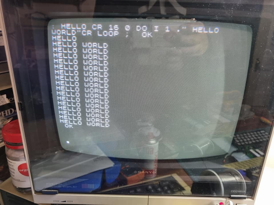
I'm very happy to say that it is now working and now for some finishing touches like building a case and finding a 200ohm speaker to use with it.
Update 4 October 2021
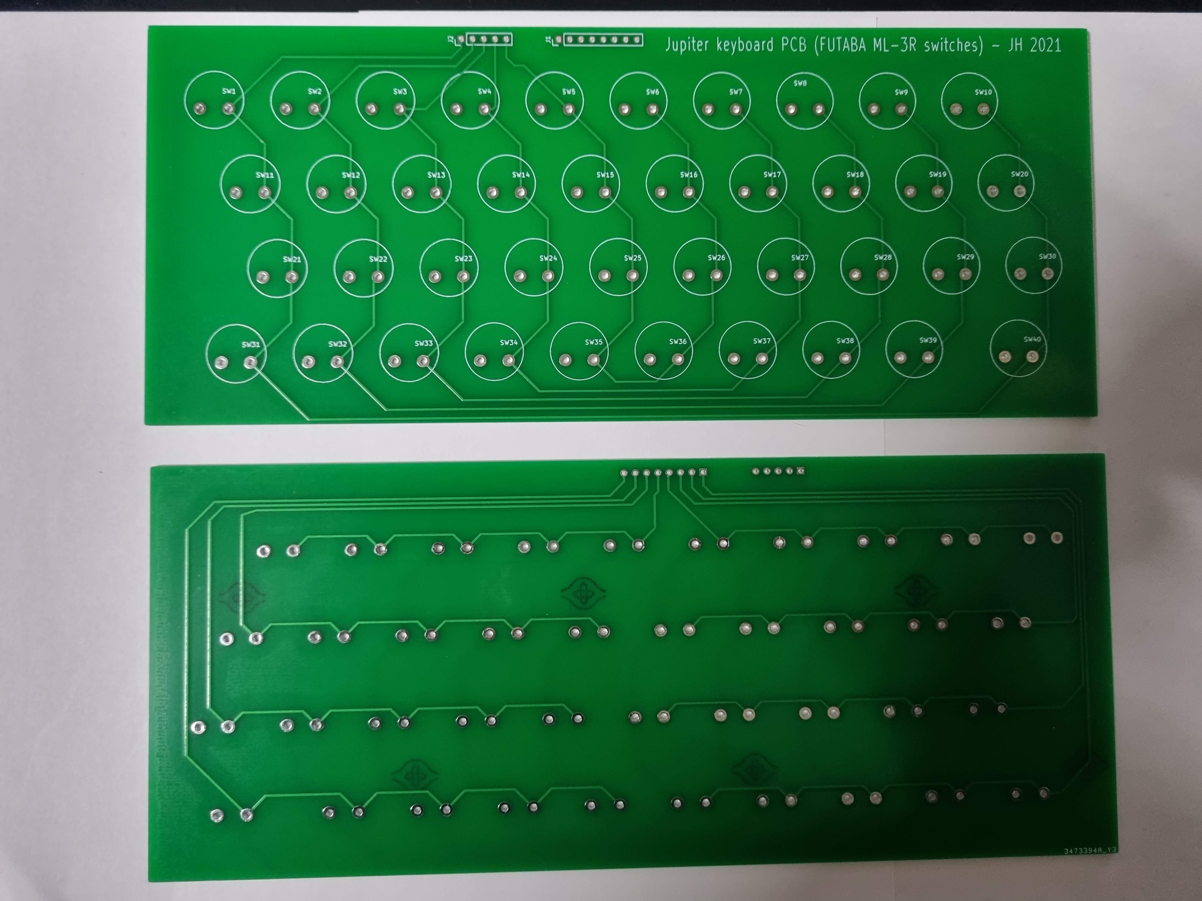
Thanks again to James Higgs who designed this PCB for FUTABA ML-3R switches, I can now create a better keyboard for the Jupiter. I will post more on this later.